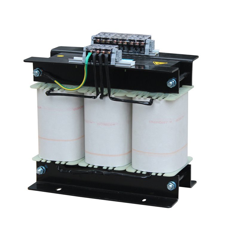
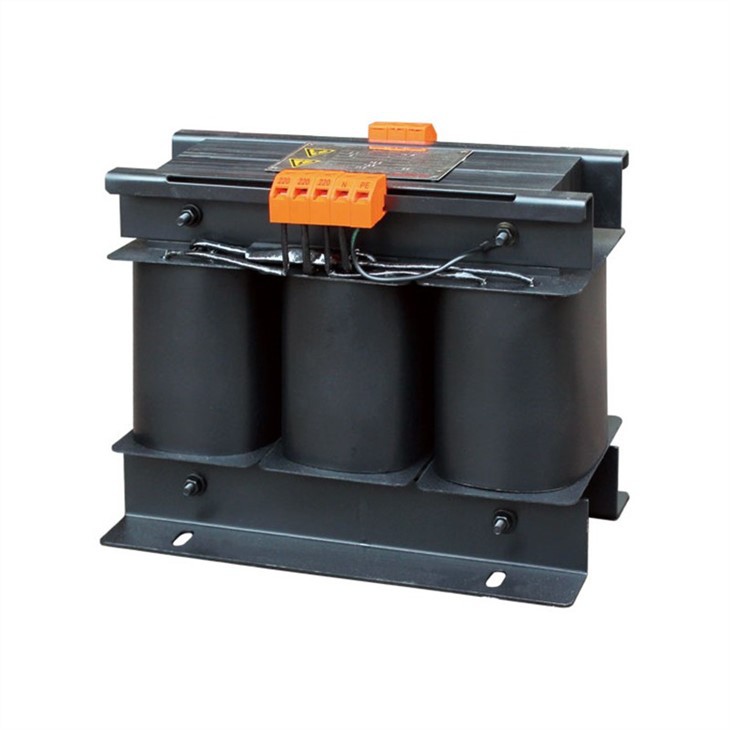
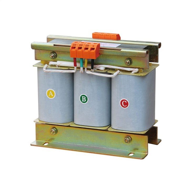
General (SBK series three-phase dry type isolation transformer)
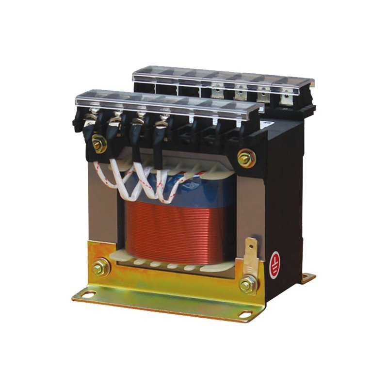
SBK series three - phase dry type transformer adopts high quality material and advanced technology, it has advantages of damp - proof and convenient maintenance, it can be applied to such power transmission and distribution places like underground railway, high building, airport, station, wharf, enterprise, tunnel, etc. It is mainly used in power supply occasions of AC 50~60Hz and voltage less than 1000V. All the input and output voltage, connection group and capacity of tapped winding can be designed and produced according to users' requirements.
Working conditions
The transformer could operate unfailingly under following condition.
1. Sea level altitude is lower than 2500M
2. Air temperature: not higher than 40ºC, and not lower than -25 ºC
3. Relative humidity: monthly average humidity is 90%.
4. A medium of no explosion hazard in where no air might corrode metal and destroy insulation, or no conductive dust existing.
5. A place of no weather effect.
Installation and use instruction
1. Unfold packing case, take out instruction, spare parts and the unit, and read “Operating instruction” carefully to ensure correct operation.
2. Fasten the transformer firmly on suitable place of airiness and heat emission to prevent it from vibration or corrosion.
3. Please test if circuitry voltage and mains voltage is rated input voltage before use it. The allowable deviation is ±5%. Please add a regulated power supply on front terminal to ensure reliable operation of transformer if the tested voltage exceeds allowable range consumedly.
4. Select lead of proper cross section and connect it according to indication, make contact after confirmed that load sharing is inerrant. For selection of cross section of lead under different conditions, please refer to following sheet:
Rated input/output current (A) | Cross section of lead (copper) (mm²) |
5 | 0.75 |
5-10 | 1.00 |
10-16 | 1.50 |
16-25 | 2.50 |
25-32 | 4.00 |
32-45 | 6.00 |
45-63 | 10.00 |
63-80 | 16.00 |
80-110 | 25.00 |
110-130 | 35.00 |
130-170 | 50.00 |
170-220 | 70.00 |
220-270 | 95.00 |
Calculating formula of rated current:
Current=Rated capability (VA)/rated output (input) voltage (V) *A
Precautions
Before purchase, please estimate total capacitance of applicable electric appliance, and choose transformer that has equivalent capacitance to prevent transformer from burning of instantaneous startup.
1.The transformer is designed and produced strictly according to relevant national standard. When using duplex winding and multi-control voltage (tap style), such as BK, JMB transformer please respectively reduce capability according to max voltage radio of primary and secondary voltage, namely, current may not exceed calculated value of max voltage; For transformer that adopts winding to divide power capacity, it is necessary to control power capacity of each winding strictly to prevent transformer from burning. For configuration and character of winding, please refer to figure 1.
2.Before installation, please check if all data listed on nameplate meet your requirement, and perform installation after confirmation.
3.After electrified, radiation (the temperature should not exceed 80℃ ) with iron core and coil of transformer is normal. If the temperature exceed 80℃, or condition of smoking occurs, please shut off power, check capacitance of electric appliance, and adjust it.
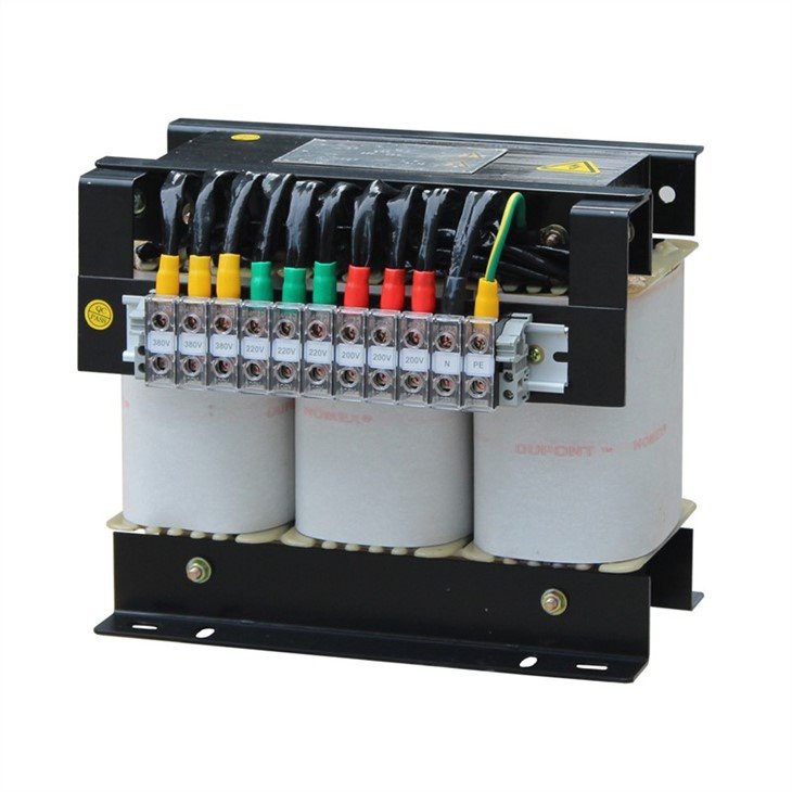
Three-phase Configuration and character of control transformer winding
 | Character of duplex winding tap style is shown as figure 1. Primary and secondary winding of transformer respectively change voltage value with lead tap of the same specification, set high-pressure level as rated value, reduce capability according to dropping radio of voltage. In case that use two kinds of voltage at output terminal synchronously, the current valued should not be exceeded (Current is rated value.) |
 | Character of multi windings of fractional power is shown as figure 2. There is one winding at primary winding, and various windings at negative pole that loads separately, hereby, each winding should not exceed specified value. |
 | Character of composite winding of fractional power is shown as figure 3. It has these two characters abovementioned, in case that change 380V of primary level to 220V, transformer capacitance should be 0.578 time of original value, current of output winding should not exceed 0.578 time of original value. |
Configuration introduction
For configuration type, please refer to figure1 and figure2.

1. Adopt three pillar iron core that made of cold rolled silicon steel plate, flux density ≥ 12000 gauss
2. According to capability, the winding will adopt SBECR double fiberglass packed flat copper wire, QZ high strength enameled wire or copper bar.
3. Insulation level: level B
Basic parameter
1. Apply to circuit below 50HZ 1000V
2. Rated working system: short term working system and long term working system.
3. Major capability, please refer to Sheet 1
SN | Specification and capability | SN | Specification and capability |
1 | SG/SBK-300VA | 14 | SG/SBK-8000 VA |
2 | SG/SBK-500 VA | 15 | SG/SBK-10KVA |
3 | SG/SBK-750 VA | 16 | SG/SBK-15 KVA |
4 | SG/SBK-1000 VA | 17 | SG/SBK-20 KVA |
5 | SG/SBK-1500 VA | 18 | SG/SBK-25 KVA |
6 | SG/SBK-2000 VA | 19 | SG/SBK-30 KVA |
7 | SG/SBK-2500 VA | 20 | SG/SBK-40 KVA |
8 | SG/SBK-3000 VA | 21 | SG/SBK-50 KVA |
9 | SG/SBK-3500 VA | 22 | SG/SBK-60 KVA |
10 | SG/SBK-4000 VA | 23 | SG/SBK-100 KVA |
11 | SG/SBK-5000 VA | 24 | SG/SBK-150 KVA |
12 | SG/SBK-6000 VA | 25 | SG/SBK-200 KVA |
13 | SG/SBK-7000 VA | 26 | SG/SBK-300 KVA |
Please select combination of rated power voltage and rated output voltage according to Sheet 2 preferentially.Sheet 2
Rated power voltage | Rated output voltage |
660 380 220 127 | 380 220 127 110 36 24 12 6 |